Welded Steel Preparation Process
The following information outlines the welded steel preparation process for steel tanks, stacks, ducts or other fabricated equipment for fluroropolymer linings. These steps need to be completed prior to the transport of the equipment to Electro Chemical for fluroropolymer lining implementation.
Watch our process video and then follow the instruction steps below:
A. Material
Material shall be new, full weight steel, free from laminations or other physical imperfections. All plates shall be flat, with no appreciable buckle or warpage. All sharp edges on sheared plates must be removed, especially on the inside of tanks. The thickness and weight per square foot shall be within the A.S.T.M. and A.N.S.I. mill tolerances as shown.
| Plate Thickness | Pounds Per Square Foot |
|---|---|
| 12 Gauge 7/64″ (.1046) | 4.385 |
| 10 Gauge 9/64″ (.1345) | 5.63 |
| 3/16″ | 7.65 |
| 1/4″ | 10.2 |
| 5/16″ | 12.3 |
| 3/8″ | 15.3 |
| 7/16″ | 17.9 |
| 1/2″ | 20 |
All dimensions and tolerances shall be specified. Fabrication dimensions must allow for lining
thickness, with particular attention to hinged covers, sight glasses and lined bolt holes. Critical
dimensions will be so identified.
C. Construction
1. Tanks or welded parts shall be fabricated in accordance with standard industry practice to obtain a practical product and uniform quality.
2. All tanks shall be constructed with a minimum number of pieces. Rectangular tanks of the open top type shall be properly reinforced in accordance with accepted practice in order to provide adequate structural strength to prevent bulging. This refers to minimum structure requirements on tanks for coating or lining. A print or other information, showing the required reinforcements, is to be supplied, in which case these reinforcements are to be figured according to print or special information transmitted with inquiry.
Where tanks or equipment have unlined, sealed false bottoms, or sealed compartments, venting of compartments must be provided to prevent rupture due to expansion of entrapped air during any hot air cure or baking process.
3. The companion flanges of sectional tanks which are bolted together must be square, plumb and smooth. Sections must fit exactly when bolted together. The open ends of sectional tanks shall be provided with suitable bracing so they will not become distorted in transit. In order to accurately indicate their position when assembled, sectional tanks shall be
permanently match marked on spots that are not to be covered with elastomers or polymers.
4. Fabricator shall supply necessary bolts, nuts, washers and gaskets to complete any assembly shown on the drawings.
5. On tanks with dished or conical heads, the dished or conical heads are to be flanged in such a manner as to eliminate wrinkles at the knuckle radius. No undercut welds are permitted.
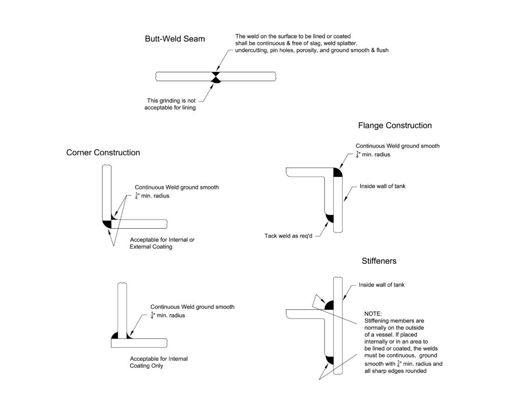
D. Welding and Grinding
1. All welded joints and seams that will be coated or lined shall be ground flush with adjacent metal and shall be smooth, solid and continuous, free of holes, porosity, lumps, high spots,
sharp edges, undercutting and pockets. Weld defects shall be repaired. See sketches for welding fabricating requirements on these surfaces.
2. All corners and all weld seams are to be ground to a minimum radius of 1/4”.
3. Partitions, braces, supports or other attachments on the inside of the tank must be fitted flush against the adjacent surface and full welded from all sides. Spot welding is not
permissible. (Welds are to be ground per (1) above.)
4. All body and bottom seams must be butt welded with continuous solid welding throughout. Lap seams are not allowed. All welding must develop strength equal to or greater than
80% of the strength of the adjoining parent metal. Vendor shall assume all responsibility for strength of welds and submit weld design and specifications when requested.
5. On pressure or vacuum tanks (or on other items specified) all fabrication shall be in accordance with the A.S.M.E. code for unfired pressure vessels. Quality of weld and the weld de
posit shall equal that specified by the code. When a fully inspected and stamped code vessel is required, it should be specified on print and order.
6. Misalignment of plates at butt weld seams shall not exceed 1/32”.
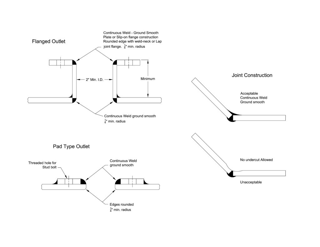
E. Outlets
1. The size, construction and location of outlets shall be in accordance with instructions on the order or print, or both. All flanges must be parallel with the tank, so that the pipe line will leave the tank at right angles to the surface of the same, unless otherwise ordered. For all closed vessels, suitable for protective lining, all manholes shall be not less than 20” in diameter, 24” diameter is preferred.
2. Pad outlets are to be continuously welded. Tapped holes may extend through pad but not into tank shell.
3. Vacuum service: Pad outlets of vacuum tanks are to be made of steel plate. No cast iron or cast steel is permitted.
4. Threaded outlets are not permitted on vessels to be lined or coated.
F. Domes and Fittings
When cast iron or steel domes and fittings are specified, they shall be free from porosity and sand holes.
G. Tests
1. Pressure
Either test or working pressure, or both, of closed tanks shall be specified on the order, specification, print. If no pressure requirements are specified, all closed cylindrical storage tanks shall be thoroughly tested for leaks.
2. All tests by vendor may be observed by Electro Chemical or final customer’s representative on request.
3. If required by Electro Chemical or final customer, the vendor shall furnish affidavit of tests.
H. Inspection
Electro Chemical and/or final customer reserves the right to inspect all tanks at the vendor’s plant, both during fabrication and on completion.
I. Rejection
Failure of a tank to meet the above specifications in any detail shall constitute sufficient cause for rejection of such tank and for it to be returned to the vendor at the vendor’s expense.
J. Shipment
Tanks shall be loaded and secured for shipment in such a manner as to insure delivery to Electro Chemical in first-class condition. If the weight exceeds 1,000 lbs., such weight is to be painted on the tank in a conspicuous place. Cylindrical tanks with manholes shall be loaded with manholes 45º from bottom.
Open top rectangular tanks shall be loaded with open side upward unless prohibited by lack of clearance.
Please contact us for assistance with preparing welded steel tanks, stacks, ducts or other fabricated equipment for fluoropolymer lining.